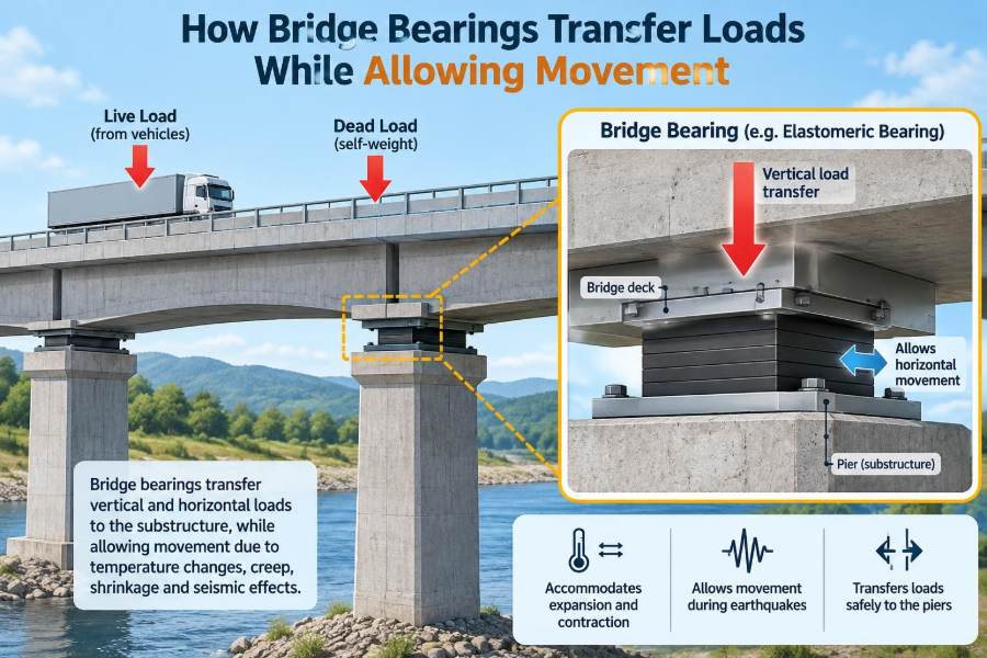

A bridge can look completely still while carrying traffic, but it is never truly motionless. A hot afternoon lengthens its deck. A cold night shortens it. Heavy trucks press the structure down, wind pushes it sideways, and concrete slowly changes shape over time.
Those movements may be small, often measured in millimetres, but a bridge is a long, stiff structure. If its supports prevented every natural movement, forces would accumulate in places not intended to resist them: piers, abutments, girders, deck joints, and connections.
Bridge bearings solve this seemingly contradictory requirement. They provide a controlled path for enormous vertical loads while permitting selected rotations and translations between the superstructure and the substructure.
For students, bearings are a useful lesson in structural behaviour. For practitioners, they are a reminder that a relatively small component can govern durability, inspection needs, constructability, and even the safety of an entire bridge.
🌉 The Basic Job of a Bridge Bearing
A bridge bearing is an interface placed between the superstructure—typically the deck and girders—and the substructure, such as piers and abutments. Its primary job is to transfer reactions safely from the bridge above to the supports below.
At the same time, it prevents the bridge from becoming unintentionally locked in place. A bearing may allow the deck to rotate, slide longitudinally, move laterally, or perform some combination of these actions, depending on its location and design.
⬇️ Following the Load Path
Understanding bearings starts with the load path. Vehicle loads, the deck’s self-weight, surfacing, barriers, and other permanent loads pass through the deck system into girders or other main members. At support locations, these forces enter the bearings.
The bearings distribute those reactions into bearing pedestals, pier caps, columns, foundations, and finally the ground. If any interface in this chain is poorly detailed, misaligned, or deteriorated, the intended load path can change.
Bearings do not “create” support capacity. They make sure the capacity of the supporting structure is engaged in the controlled manner assumed by the design.
⚖️ Vertical Load Is Only Part of the Story
The most visible bearing action is vertical compression. The bearing must resist the downward reaction from dead load and traffic without crushing, excessive deformation, or unstable behaviour.
Yet vertical support alone would be easy: a fixed concrete block could carry compression. The engineering challenge is that a bridge deck also needs freedom to change length and rotate under ordinary service conditions.
Therefore, bearing selection is about which degrees of freedom are restrained and which are released. The answer differs from one support to another.
🌡️ Why Temperature Makes Bridges Move
Most bridge materials expand when heated and contract when cooled. For a long bridge, a modest temperature change can produce a meaningful change in overall length, especially when the deck is exposed to sunlight while its supports remain relatively shaded.
A simplified thermal movement estimate is the material’s coefficient of thermal expansion multiplied by the temperature change and member length. Designers refine this basic idea by considering bridge geometry, material type, temperature ranges, and how temperatures vary through the section.
The key point is practical: thermal movement is predictable enough that the bridge must be detailed to accommodate it, not treated as an unusual event.
🔄 Rotation at the Supports
Girders bend under their own weight and under traffic. As they bend, their ends rotate slightly at the supports. A bearing must accommodate this rotation without concentrating damaging stress at an edge.
Imagine placing a rigid book flat on a table and gently bending it. Its contact pressure would shift toward one edge. Bearings use deformable layers, curved elements, sliding surfaces, or shaped components to maintain suitable contact as the supported member rotates.
Rotation demand can be especially significant near continuous-span piers, where bending moments and support conditions differ from those of simple spans.
↔️ Translation in Different Directions
Translation means movement without rotation. The most common requirement is longitudinal movement, along the length of the bridge, caused largely by temperature effects, shrinkage, creep, and prestress-related shortening.
Some bridges also need lateral movement because of skew geometry, curved alignment, wind effects, seismic displacement demands, or differential movements of supports. A bearing should allow only the movement its system requires; unrestricted motion in every direction may leave the bridge insufficiently restrained.
📍 Fixed, Guided, and Free Support Lines
Bridge supports are commonly assigned different movement roles. A fixed bearing location anchors the superstructure in selected horizontal directions and transfers corresponding forces into the substructure. Expansion bearings permit movement in one or more directions away from that anchor.
A guided bearing allows translation in a specified direction while restraining it perpendicular to that direction. A free-sliding bearing can permit movement in two horizontal directions, subject to the specific bearing configuration and restraint system.
These labels describe behaviour, not merely product names. The complete bridge system—including shear keys, dampers, joints, and abutment details—must be reviewed together.
🧭 Choosing the Fixed Point
The fixed point is often positioned to limit total movement at expansion joints and to direct horizontal forces efficiently into robust supports. On a short, straight bridge, this may appear straightforward. On a long, skewed, curved, or irregular bridge, the decision affects many components.
Placing the fixed point near the middle can reduce maximum thermal travel toward either end, while placing it at an abutment can simplify other aspects of the system. Neither approach is universally best.
Designers must consider foundation stiffness, seismic strategy, construction sequence, joint capacity, and how load redistribution may occur if one support behaves differently than assumed.
🧱 Elastomeric Bearings: Flexible Rubber-Steel Laminates
Elastomeric bearings are widely used because they are compact and have no conventional sliding or mechanical parts. They consist of rubber-like elastomer layers, often reinforced with thin steel plates bonded inside the bearing.
Vertical load compresses the bearing. Rotation is accommodated by deformation of the elastomer, while small horizontal movements occur through shear deformation. The internal steel layers restrain lateral bulging and improve vertical stiffness.
They work particularly well where movement and rotation demands are moderate. Their simplicity can reduce maintenance needs, but it does not eliminate the need for inspection.
🧪 What the Shape Factor Changes
In a laminated elastomeric bearing, the shape factor describes the relationship between a loaded rubber layer’s plan area and the free area through which it can bulge. It strongly influences vertical stiffness and stress behaviour.
Thin elastomer layers between steel shims are laterally confined, making the bearing much stiffer vertically than a plain rubber pad of similar overall thickness. At the same time, the bearing remains relatively flexible in horizontal shear.
This is why bearing design cannot rely on material softness alone. Geometry, reinforcement, bonding, shear strain, compression, and rotation all interact.
🛷 Sliding Bearings and Low-Friction Surfaces
Where movements are larger than practical elastomer shear deformation can accommodate, sliding bearings are often used. These systems commonly combine a polished metal surface with a low-friction polymer sliding layer.
The bearing carries vertical load through one component while allowing translation along the sliding interface. Proper contact pressure, surface finish, sealing, alignment, and contaminant control are central to reliable performance.
A sliding bearing is not frictionless. Resistance to motion must be considered because it affects horizontal reactions, thermal force buildup, and the forces transferred to piers and abutments.
⚙️ Pot Bearings and Their Sealed Elastomer
A pot bearing confines an elastomeric disc within a steel pot. Under high pressure, the confined elastomer can behave in a way that allows rotation, while separate sliding components may provide translation.
This makes pot bearings useful where reactions are high and rotational demands exceed what a compact elastomeric pad can comfortably handle. However, their steel components, seals, and sliding surfaces require careful fabrication, installation, and access for inspection.
The term “pot” refers to the steel container, not a reservoir of loose material. The behaviour depends on a deliberately confined elastomer element.
🔵 Spherical and Cylindrical Bearings
Spherical bearings use curved interfaces to accommodate rotation about more than one axis. Cylindrical bearings primarily accommodate rotation about one axis, making them suitable where movement is largely directional.
These bearings can carry high loads in relatively compact assemblies. Translation is often added through a separate sliding surface, so the final unit may provide vertical support, rotation, and guided or free movement.
Their precision components make correct orientation essential. Installing a guided direction incorrectly can create restraint in the wrong direction and alter the bridge’s intended response.
🪨 Rocker and Roller Bearings in Older Bridges
Older bridges may contain rocker, roller, or pin-type bearings. These historic systems used visible mechanical movement to permit rotation or expansion, and they can still be found in service.
They also illustrate why exposure matters. Corrosion, seized rollers, debris, loss of alignment, and worn contact surfaces can prevent intended movement. Once motion is restrained, thermal forces may be redirected into members that were not intended to receive them.
Replacement decisions require investigation rather than assumptions. The existing structure may have adapted to the old bearing’s actual behaviour over decades.
📐 Bearing Orientation Matters on Skewed Bridges
A skewed bridge crosses its support line at an angle rather than at 90 degrees. When the deck expands, its movement relative to supports and joints can become more complex than the simple “straight along the bridge” picture.
Guides, sliding directions, and joint details must be coordinated with the structural analysis and geometric layout. A bearing aligned purely by visual convenience may not match the intended movement vector.
Curved bridges add another layer of complexity. Radial, tangential, and chord-direction movements may need explicit consideration, especially when multiple supports interact.
🏗️ Bearing Layout Is a System Decision
A bearing schedule often lists reactions, movement capacities, rotations, types, orientations, and anchor details at each location. But a schedule alone does not demonstrate sound behaviour; it is a summary of the system design.
Engineers should check how individual bearings work collectively. For example, two supports both assumed to be “fixed” may unintentionally over-restrain thermal movement if their foundations or pier caps are stiff enough to attract significant force.
- Where horizontal loads are intended to go
- Which supports permit longitudinal and transverse movement
- How deck joints accommodate movement
- Whether restraint components activate under seismic or wind loading
🌪️ Wind, Braking, and Seismic Forces
Bearings may transfer more than gravity loads. Wind can apply lateral loads, vehicle braking can induce longitudinal forces, and seismic actions can impose complex combinations of displacement, acceleration, uplift, and shear.
Some bearing systems are designed to carry service-level horizontal loads while allowing thermal movement. Others work with separate shear keys, restrainers, isolation devices, or dampers that engage under particular conditions.
Seismic design is highly location- and code-dependent. It should never be reduced to simply choosing a “stronger bearing”; the dynamic response of the full bridge, foundations, and restraint strategy matters.
🧷 Uplift and Unseating Risks
Not every support reaction is compressive under every load combination. Curved geometry, wind, seismic effects, construction stages, cantilever actions, and certain continuous-span conditions can create uplift or reduced compression at bearings.
Where uplift is possible, bearings and anchorages may need to resist tension or a separate hold-down arrangement may be required. A bearing designed only for downward pressure can separate or become unstable when the assumed contact condition disappears.
Support-seat length also deserves attention. It provides physical tolerance for movement and helps reduce the risk of a girder losing adequate support during extreme displacement events.
🧰 Designing for Real Movement, Not Ideal Drawings
Calculated movement is only one part of bearing capacity. Real bridges face construction tolerances, girder camber variation, bearing pad elevation differences, temperature at installation, and gradual material changes.
Concrete shrinkage and creep can shorten or redistribute forces in concrete bridges over time. Prestressed members may also experience long-term length changes. Steel and concrete composite systems can respond differently as temperatures vary through their components.
Good detailing includes reasonable allowance for these effects rather than assuming every member begins in a perfect, stress-free position.
🌤️ Installation Temperature and Preset Positions
Some expansion bearings are installed at a preset position rather than centered in their travel. The target setting depends on the deck temperature during installation and the movement expected before the bridge reaches its design temperature extremes.
If a bearing is set incorrectly, it may use much of its available travel in one direction. The bridge can then reach a limit stop, overstress a guide, or impose unexpected force on the fixed support.
Installation records should document bearing type, location, orientation, preset condition, elevations, and the temperature information required by the project specifications.
🔩 Anchor Bolts, Sole Plates, and Bearing Pedestals
The bearing body is only one part of the assembly. Sole plates connect it to the girder, masonry plates distribute force into concrete, anchor bolts resist specified horizontal or uplift actions, and pedestals provide elevation and a level support surface.
These details must have sufficient stiffness and reinforcement to spread concentrated loads. Thin plates can bend, poorly grouted beds can leave unsupported zones, and inadequate edge distances can damage concrete around anchors.
Clear detailing also helps future work. Crews need room to inspect, jack, remove anchors where intended, and replace a bearing without improvising around inaccessible components.
🧱 Grout, Levelness, and Full Contact
Bearings are designed around assumed contact areas. An uneven pedestal, voided grout, debris, or a tilted plate can concentrate pressure at one corner and reduce the effective load-bearing area.
For sliding systems, poor levelness can cause unintended drift or uneven contact. For elastomeric pads, severe misalignment can produce uneven bulging and excessive local strain.
Field quality control should verify surfaces before placement, not after the bridge load has made correction difficult. Small geometric errors at this interface can have outsized consequences.
🔍 What Inspectors Look For
Bearing inspections look for evidence that the component is carrying load and moving as intended. Access conditions vary widely, but an organized inspection considers both the bearing and its surrounding structural clues.
- Cracked, bulging, hardened, or displaced elastomer
- Corrosion, missing fasteners, fractured welds, or damaged coatings
- Debris blocking sliding paths or drainage water reaching the assembly
- Misalignment, uneven contact, abnormal tilt, or excessive plate deformation
- Joint distress, cracked pedestals, or unexpected marks suggesting movement has reached a limit
Observations should be interpreted in context. A dirty bearing is a maintenance concern; a seized bearing combined with cracking near a restraint location may indicate a more consequential system problem.
💧 Drainage and Debris Are Bearing Enemies
Bearings often sit below deck joints, exactly where leaking water, deicing chemicals, grit, and road debris can collect. This environment accelerates corrosion and can contaminate sliding surfaces.
Good bridge detailing directs drainage away from bearings where practical and provides accessible paths for cleaning. Joint leakage should not be treated as an isolated deck issue when it is dripping directly onto critical support hardware.
Protective coatings, stainless components, seals, and shields can help, but none replaces sensible drainage and routine maintenance.
🚧 Common Design and Construction Mistakes
Many bearing problems begin not with exotic failure modes but with coordination errors. These mistakes can be difficult to correct after girders are erected and the deck has been cast.
- Specifying movement capacity without checking the actual fixed-point arrangement
- Mixing up guided and free bearing orientations
- Ignoring construction-stage reactions and rotations
- Leaving inadequate access for inspection, jacking, or replacement
- Failing to coordinate joint movement range with bearing movement range
- Installing bearings on unprepared, non-level, or contaminated surfaces
A bearing should be reviewed as part of the bridge’s geometry, structural analysis, detailing, and maintenance plan—not as a catalogue item added late in design.
🏋️ Jacking and Bearing Replacement
Bearings are sometimes replaced because of deterioration, functional obsolescence, damage, or a bridge rehabilitation project. This is a demanding operation because the existing bridge may not distribute forces exactly as its original drawings suggest.
Engineers develop a jacking scheme that identifies lift points, load paths, permissible differential movement, temporary bracing, traffic restrictions, and monitoring. Even a small lift can affect deck joints, utilities, diaphragms, and adjacent bearings.
Replacement is therefore a structural intervention, not routine hardware swapping. Site verification and staged work are essential.
📊 A Practical Comparison of Bearing Families
| Bearing family | Typical movement approach | Common strengths | Key considerations |
|---|---|---|---|
| Elastomeric | Elastomer shear and deformation | Simple, compact, few exposed moving parts | Limited practical movement range; check strain, rotation, and durability |
| Sliding | Low-friction interface | Accommodates larger translation | Friction, contamination, wear, and alignment affect behaviour |
| Pot | Confined elastomer rotation, often with sliding surface | High reactions and compact rotational capacity | Seals, steelwork, and maintenance access require attention |
| Spherical/cylindrical | Curved rotational surface, often with sliding surface | High load and defined rotational behaviour | Precision orientation and protection of interfaces are critical |
Actual selection depends on project-specific reactions, movements, rotations, environment, construction method, inspection access, and governing requirements. No single family is inherently best.
🧠 A Simple Mental Model for Students
Think of the bridge deck as a long ruler resting on several supports. Pressing down represents gravity load; the supports must hold it up. Warming the ruler makes it longer; at least some supports must let it slide rather than forcing it to buckle or build excessive force.
Bending the ruler makes its ends change angle; the supports must tolerate that rotation. Pushing sideways represents wind or seismic action; selected restraints must provide a controlled resisting path.
This analogy is simplified, but it captures the central design question: support the required loads while releasing the required movements.
📝 Questions to Ask During Design Review
A useful bearing review asks more than whether the listed vertical capacity exceeds the calculated reaction. It tests whether the design intent remains coherent from analysis through construction and maintenance.
- What movements and rotations are expected at each support?
- Where is the bridge fixed, and what horizontal forces reach that location?
- Do bearing guides align with the intended movement directions?
- Are thermal, long-term, construction, and extreme-event conditions considered?
- Can drainage, inspection, jacking, and replacement be performed safely?
- Do the bearings, joints, shear keys, and seats have compatible displacement capacities?
Clear answers to these questions often reveal coordination issues before they become site problems.
🎯 The Core Principle: Controlled Freedom
Bridge bearings are not passive blocks placed under girders. They are engineered devices that define the relationship between a bridge and its supports. Their performance depends on the loads they transfer, the movements they permit, and the restraints they intentionally provide.
A successful arrangement recognizes that a bridge must move in ordinary service. It provides enough vertical stiffness to carry reactions, enough rotational capacity to follow girder deflection, and enough translational freedom to avoid unwanted thermal restraint.
At the same time, it establishes deliberate load paths for horizontal, uplift, and extreme-event demands. That balance—neither completely fixed nor completely free—is the essence of bearing design.
Bridge bearings keep a bridge stable by giving it precisely the freedom it needs to move. When their behaviour, detailing, installation, and maintenance are treated as one connected system, the bridge can carry load reliably while adapting to everyday change. 🏗️🌉🔧