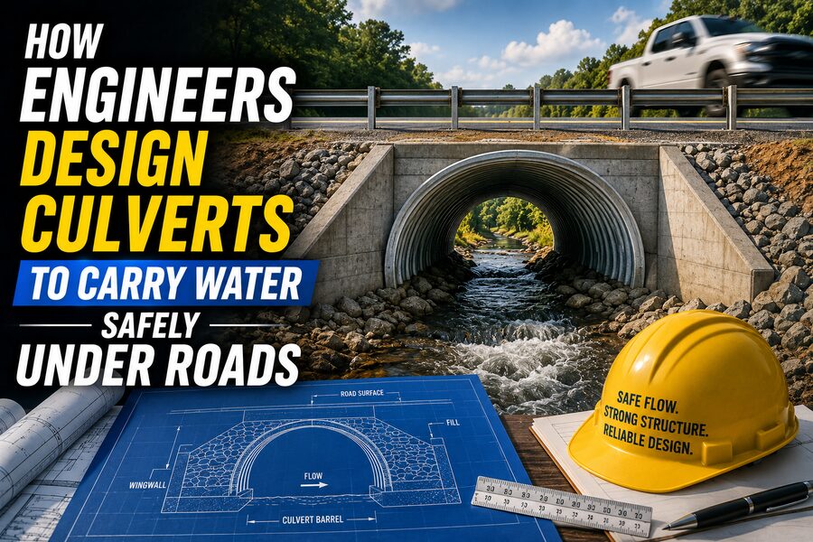

Roads frequently cross streams, drainage channels, roadside ditches, and low-lying areas where water naturally wants to flow. If engineers simply built a solid road embankment across these paths, water would collect on the upstream side, flood nearby land, erode the roadway, or eventually wash the road away. 🌧️🛣️
To prevent this, engineers install culverts—structures that allow water to pass safely beneath roads, railways, driveways, and embankments.
A culvert may look like a simple pipe, but designing one properly requires much more than choosing a diameter and burying it under the road. Engineers must consider rainfall, watershed size, stream flow, debris, erosion, soil conditions, roadway elevation, environmental impacts, and the consequences of flooding.
A well-designed culvert must do two things at the same time:
Carry enough water during storms while keeping the road and surrounding land safe. 💧🏗️
🧱 What Is a Culvert?
A culvert is a hydraulic structure that conveys water through or beneath an obstruction such as a road embankment.
Common culvert shapes include:
- Circular pipes
- Box culverts
- Arch culverts
- Elliptical pipes
- Pipe arches
They may be constructed from materials such as:
- Reinforced concrete
- Corrugated metal
- High-density polyethylene
- Masonry
- Structural steel
The choice depends on hydraulic requirements, structural loading, durability, cost, and site conditions.
Some culverts carry only occasional stormwater.
Others carry permanent streams year-round. 🌊
🌧️ Step 1: Estimate How Much Water May Arrive
Before sizing a culvert, engineers need to estimate the amount of water that may reach the crossing.
This begins with the drainage basin, also called a watershed or catchment.
The watershed is the land area where rainfall drains toward the culvert location.
Important characteristics include:
- Watershed area
- Ground slope
- Soil type
- Vegetation
- Urban development
- Rainfall intensity
- Existing streams and channels
A small wooded watershed may produce relatively modest runoff.
A similarly sized urban watershed covered with pavement and rooftops can generate much larger peak flows because less rainfall soaks into the ground. 🏙️🌧️
📊 Understanding Design Storms
Culverts are not designed only for everyday rainfall.
Engineers evaluate larger storms that have specific statistical probabilities of occurring.
These may be described using return periods, such as:
- 2-year storm
- 10-year storm
- 25-year storm
- 50-year storm
- 100-year storm
A “100-year storm” does not mean it happens exactly once every 100 years.
It means a storm of that magnitude has approximately a 1% annual probability of being exceeded in any given year.
Two such storms could theoretically occur within a short period.
The design return period depends on factors such as roadway importance, local regulations, flood consequences, and public safety. ⚠️
🧮 Estimating Peak Runoff
For small drainage basins, engineers may use simplified methods such as the Rational Method.
Conceptually:
Q = C × I × A
where:
Q= peak dischargeC= runoff coefficientI= rainfall intensityA= drainage area
The runoff coefficient represents how much rainfall becomes surface runoff.
A paved parking lot has a high runoff coefficient because most water flows over the surface.
A forested basin has a lower coefficient because more water infiltrates into soil or is intercepted by vegetation.
For larger watersheds, engineers may use more advanced hydrologic models that simulate rainfall, infiltration, storage, and channel routing. 📈
🌊 Step 2: Determine How the Water Will Flow Through the Culvert
Once the design discharge is estimated, the next question is:
Can the proposed culvert pass that flow safely?
Water behavior inside a culvert can be surprisingly complex.
Depending on conditions, the culvert may flow:
- Partially full
- Completely full
- Under open-channel flow
- Under pressurized flow
The governing hydraulic behavior depends on water depth upstream, culvert slope, shape, roughness, length, and downstream conditions.
Engineers often distinguish between inlet control and outlet control.
🚪 What Is Inlet Control?
Under inlet control, the main restriction occurs at the entrance to the culvert.
The culvert barrel downstream may have enough capacity, but water cannot enter fast enough.
Inlet performance depends on:
- Culvert opening size
- Entrance shape
- Headwall geometry
- Upstream water depth
- Culvert shape
A sharp-edged entrance may create more energy loss than a carefully shaped inlet.
Improving the entrance can sometimes increase culvert capacity without changing the entire barrel. ⚙️
🚰 What Is Outlet Control?
Under outlet control, flow is influenced by the entire culvert system.
Factors include:
- Culvert length
- Internal roughness
- Slope
- Entrance loss
- Exit loss
- Downstream water level
In this situation, friction along the culvert barrel becomes important.
A long rough culvert may carry less water than a short smooth culvert with the same diameter.
Engineers calculate both inlet and outlet control conditions and use the one that produces the more critical upstream water level.
📏 Why Culvert Diameter Matters
A larger culvert opening can carry more water.
However, simply making the pipe extremely large is not always economical.
Larger structures cost more to purchase, transport, install, and bury.
The engineer therefore seeks a size that:
- Passes the required flow
- Keeps upstream flooding acceptable
- Limits outlet velocity
- Provides debris clearance
- Meets structural requirements
- Remains economically reasonable
Sizing is therefore an optimization problem rather than merely a hydraulic calculation. 💰
🌊 Headwater: The Water Level Upstream
When stormwater reaches a culvert faster than the structure can pass it, water begins to pond upstream.
The resulting upstream depth is called the headwater.
Some headwater is often acceptable.
But excessive headwater can cause:
- Road overtopping
- Flooding of nearby property
- Embankment erosion
- Damage to utilities
- Unsafe conditions
Engineers therefore compare the predicted headwater elevation with the road elevation and nearby property levels.
A key design objective is usually to maintain enough freeboard between floodwater and the roadway surface. 🛣️
🌊 Tailwater: The Water Level Downstream
The water level downstream of the culvert is called the tailwater.
Tailwater can strongly influence culvert performance.
For example, if the downstream stream is already flooded, water may back up into the culvert.
High tailwater can reduce the hydraulic gradient through the structure and increase upstream water levels.
Engineers therefore evaluate both upstream and downstream conditions rather than treating the culvert as an isolated pipe.
🏃 Water Velocity Is Just as Important as Capacity
A culvert might successfully pass the design flow but still create another problem: excessive outlet velocity.
When water is squeezed through a culvert, it may accelerate dramatically.
Fast-moving water leaving the outlet can erode:
- Streambeds
- Road embankments
- Downstream banks
- Nearby property
This process is called scour.
A culvert that survives the storm while destroying the downstream channel is not a successful design. 🌊⚠️
🪨 Protecting Against Scour
Engineers use several methods to control erosion near culvert outlets.
These may include:
- Riprap
- Concrete aprons
- Energy-dissipation basins
- Stillings basins
- Vegetated channels
- Outlet structures
Riprap consists of large stones placed where high-velocity water could erode soil.
The rocks absorb and spread hydraulic energy.
In more severe cases, specially designed energy dissipators reduce flow velocity before water enters the natural channel.
🧱 Headwalls and Wingwalls
Many culverts include concrete or masonry structures at their ends.
A headwall surrounds the culvert opening and helps:
- Retain the road embankment
- Stabilize the inlet or outlet
- Guide flow
- Protect against erosion
Wingwalls extend outward from the headwall.
They help transition water between the natural channel and the culvert opening.
Well-shaped headwalls can improve hydraulics while also protecting the soil around the structure. 🏗️
🪵 Debris Can Block a Culvert
Real stormwater often carries more than water.
It may contain:
- Branches
- Leaves
- Logs
- Trash
- Sediment
- Ice
A culvert sized only according to theoretical flow capacity may fail if debris blocks its inlet.
This is especially important in wooded watersheds and mountainous regions.
Engineers may provide:
- Larger openings
- Multiple barrels
- Debris racks
- Improved inlet geometry
- Maintenance access
However, debris racks themselves can become clogged, so they must be used carefully.
Maintenance planning is therefore part of hydraulic design. 🧹
🏞️ Culvert Alignment Matters
Ideally, a culvert follows the natural direction of water flow.
Poor alignment can force water to make sharp turns.
This increases energy loss and may cause erosion.
Engineers try to align the structure with the existing channel wherever possible.
If the road crosses the stream at an angle, the culvert may need to be longer or skewed beneath the roadway.
Good alignment helps water enter and exit smoothly.
📐 Culvert Slope
The culvert’s longitudinal slope affects:
- Flow velocity
- Hydraulic capacity
- Sediment movement
- Fish passage
- Scour risk
A steep culvert may carry water quickly but create extremely high outlet velocities.
A nearly flat culvert may encourage sediment deposition.
The designer therefore tries to match the natural channel slope when practical while maintaining adequate drainage.
🪨 Sediment Transport
Streams naturally transport sediment such as sand, gravel, and silt.
A poorly designed culvert can interrupt this movement.
If water slows inside the culvert, sediment may settle and gradually reduce the opening.
If velocity becomes too high, the structure may erode the downstream channel.
Engineers consider whether the culvert can remain reasonably self-cleaning while still preserving natural channel stability.
This is particularly important for culverts carrying permanent streams.
🐟 Culverts and Fish Passage
Modern culvert design often considers ecological connectivity as well as drainage.
A culvert may unintentionally become a barrier to fish and other aquatic organisms.
Problems may include:
- Excessive water velocity
- Shallow water
- Large vertical drop at the outlet
- Smooth bottoms with no resting areas
For environmentally sensitive streams, engineers may use stream-simulation culverts or embedded culverts.
These structures may contain natural gravel and rock inside the culvert so the channel resembles the streambed outside.
The goal is to maintain both hydraulic and biological connectivity. 🐟🌿
🛣️ Road Overtopping
Even a properly designed culvert can encounter a storm larger than its design event.
Engineers therefore ask:
What happens if the culvert capacity is exceeded?
In some locations, water may safely flow over a low roadway without causing catastrophic damage.
In other locations—such as major highways—road overtopping may be unacceptable.
Designers evaluate:
- Overtopping depth
- Water velocity
- Embankment erosion
- Traffic safety
- Emergency access
This is part of designing for failure modes, not just ordinary operation. ⚠️
🏗️ Structural Design of the Culvert
Culverts must resist more than water pressure.
They also support the weight of the road and traffic above.
Structural loads may include:
- Soil fill
- Cars
- Heavy trucks
- Construction equipment
- Groundwater pressure
A culvert buried under a deep road embankment may experience enormous compressive loads.
Engineers check whether the pipe or box can safely resist these forces.
For flexible pipes, the surrounding soil is also part of the structural system.
Proper compaction is essential.
🧱 Soil–Structure Interaction
Flexible culverts made from metal or plastic deform slightly under load.
This is expected.
As the culvert deforms, it pushes against the surrounding compacted soil.
The soil then helps support the structure.
This interaction is called soil–structure interaction.
If the surrounding soil is poorly compacted, the culvert may deform excessively.
Good installation is therefore just as important as selecting the correct pipe strength. 🚧
🔨 Bedding and Backfill
The material immediately beneath and around the culvert is called bedding and backfill.
It must provide uniform support.
Poor bedding can cause:
- Uneven settlement
- Pipe distortion
- Joint separation
- Cracking
Engineers specify:
- Bedding type
- Layer thickness
- Compaction requirements
- Backfill material
- Minimum cover depth
Construction crews must follow these requirements carefully.
📉 Settlement and Road Performance
If the culvert or surrounding soil settles after construction, the road above may develop a dip.
This can create:
- Poor ride quality
- Pavement cracking
- Water accumulation
- Maintenance problems
Proper foundation preparation and compaction help prevent differential settlement.
In weak soils, engineers may require:
- Soil replacement
- Geotextiles
- Stabilization
- Deep foundations
- Special bedding
The hydraulic structure must work together with the geotechnical design.
🔄 Multiple-Barrel Culverts
Instead of one large pipe, some crossings use several smaller culverts side by side.
These are called multiple-barrel culverts.
They can provide large total flow capacity.
However, multiple barrels may be more vulnerable to debris blockage because branches can become trapped between openings.
They can also alter sediment movement.
Engineers compare the benefits of one large opening against several smaller ones.
🧰 Maintenance Access
A culvert may operate for decades.
During that time, it may require:
- Sediment removal
- Debris clearing
- Joint repair
- Erosion repair
- Structural inspection
A design that is hydraulically excellent but impossible to maintain can become expensive over its service life.
Large culverts may allow personnel to enter for inspection under controlled conditions.
Smaller pipes may require remote cameras or flushing equipment. 🔍
🧪 Material Selection and Durability
Culvert materials face harsh conditions.
They may be exposed to:
- Water
- Soil chemicals
- Abrasion
- Corrosion
- Freeze-thaw cycles
- Sediment
Concrete provides high strength and good durability in many environments.
Metal culverts can be lightweight and quick to install but may require corrosion protection.
Plastic culverts resist corrosion and are lightweight but require proper structural support from surrounding soil.
The best material depends on site chemistry, expected life, structural loads, abrasion, cost, and availability.
❄️ Cold-Climate Considerations
In cold climates, culverts may experience:
- Ice buildup
- Frozen inlets
- Frost heave
- Snowmelt surges
A partially blocked culvert can create rapid upstream flooding during spring thaw.
Designers in cold regions may therefore consider larger openings, appropriate slopes, insulation effects, and maintenance requirements.
Climate can significantly influence drainage design.
🌡️ Climate Change and Future Rainfall
Many infrastructure agencies are increasingly considering whether historical rainfall records adequately represent future conditions.
More intense rainfall in some regions can increase peak runoff.
Because culverts may remain in service for 50 years or longer, engineers may evaluate:
- Updated rainfall intensity data
- Future climate projections
- Increased safety factors
- Larger design storms
Building some adaptability into drainage infrastructure can reduce the risk of expensive replacement later. 🌧️📈
🧠 Hydraulic Modeling
Modern engineers often use specialized computer models to evaluate culvert performance.
Models can estimate:
- Headwater elevation
- Flow velocity
- Inlet losses
- Outlet losses
- Tailwater effects
- Road overtopping
- Flood profiles
For complex crossings, two-dimensional hydraulic models may simulate how floodwater spreads across the entire floodplain.
These tools help engineers understand how the culvert interacts with surrounding terrain.
🗺️ Survey Data Is Essential
Accurate topographic information is required before hydraulic calculations begin.
Surveyors may measure:
- Channel elevations
- Road elevation
- Upstream terrain
- Downstream terrain
- Culvert location
- Stream slope
- Existing structures
Modern projects may use:
- GPS survey
- Total stations
- LiDAR
- Drone mapping
Small elevation errors can significantly affect predicted flood levels, especially in flat terrain. 📡
🚜 Construction Sequencing
Installing a culvert often requires temporarily managing water flow.
Crews may use:
- Temporary diversion channels
- Pumps
- Cofferdams
- Bypass pipes
This keeps the work area dry enough for safe construction.
Environmental regulations may restrict when work can occur in streams, particularly during fish spawning seasons.
Thus, engineering design must account for construction logistics as well as final operation.
🏙️ Culverts in Urban Drainage Systems
In cities, culverts may form part of a larger stormwater network.
Water may move through:
Street inlet → storm sewer → culvert → drainage channel
Urban runoff can rise very quickly because paved surfaces produce rapid drainage.
Blocked culverts can flood roads and buildings within minutes.
Urban culverts may therefore be integrated with detention ponds, storm sewers, and flood-control channels.
⚠️ Common Reasons Culverts Fail
Culvert failures can occur because of:
- Undersized openings
- Debris blockage
- Excessive scour
- Poor installation
- Corrosion
- Joint separation
- Foundation failure
- Sediment accumulation
- Extreme storms
A failure may begin gradually.
For example, erosion around the outlet can undermine the pipe.
Eventually, soil beneath the roadway is removed, creating a void.
The pavement may then collapse suddenly.
Regular inspection helps catch these problems early. 🔍
🛡️ Designing for Resilience
A resilient culvert is designed not only for routine flow but also for uncertainty.
Engineers may provide:
- Additional hydraulic capacity
- Erosion protection
- Redundant barrels
- Safe overflow paths
- Durable materials
- Easy maintenance access
The appropriate level of protection depends on the consequences of failure.
A culvert beneath a farm road requires a different risk strategy from one beneath an interstate highway.
💰 Balancing Safety and Cost
Making every culvert enormous would reduce flood risk but create unnecessary expense.
Engineering design balances:
Construction cost + maintenance cost + flood risk + failure consequences
A small increase in culvert size may be inexpensive during initial construction but extremely costly after the road has been completed.
For this reason, lifecycle cost often matters more than simply choosing the cheapest initial option.
🚦 A Simplified Culvert Design Process
A typical engineering workflow may involve:
- 🗺️ Survey the crossing.
- 🌧️ Define the watershed.
- 📊 Estimate design storm runoff.
- 📐 Select preliminary culvert geometry.
- 💧 Perform hydraulic calculations.
- 🌊 Check headwater and tailwater.
- 🪨 Evaluate outlet velocity and scour.
- 🧱 Perform structural design.
- 🐟 Review environmental requirements.
- ⚠️ Check extreme-event overtopping.
- 🔧 Design erosion protection and headwalls.
- 📋 Prepare construction drawings and maintenance recommendations.
Each step contributes to the final safety of the road crossing.
🏁 Final Thoughts
Culverts may be among the least noticeable structures in transportation infrastructure, but they perform an essential job every time it rains. 🌧️🛣️
Their purpose is simple:
Let water continue along its natural drainage path without allowing that water to damage the road above.
Achieving that safely requires engineers to understand both hydrology and hydraulics.
They estimate how much runoff may reach the site, determine how water will enter and pass through the culvert, predict upstream flooding, calculate downstream velocities, and protect against scour.
They must also ensure the structure can withstand soil and vehicle loads, remain durable for decades, pass debris where possible, accommodate sediment, and sometimes preserve aquatic habitat.
A culvert that is too small may flood the road.
A culvert with excessive outlet velocity may destroy the downstream channel.
A structurally weak culvert may collapse beneath traffic.
A poorly installed culvert may settle or deform even if its calculations were correct.
That is why successful culvert design combines:
Hydrology + hydraulics + structural engineering + geotechnical engineering + environmental design + maintenance planning. 🏗️🌊
When all of these elements work together, the culvert quietly carries stormwater beneath the roadway while traffic passes safely above.
Most drivers will never notice it—and in many ways, that is the sign of a culvert doing its job perfectly. 🚗🌉💧