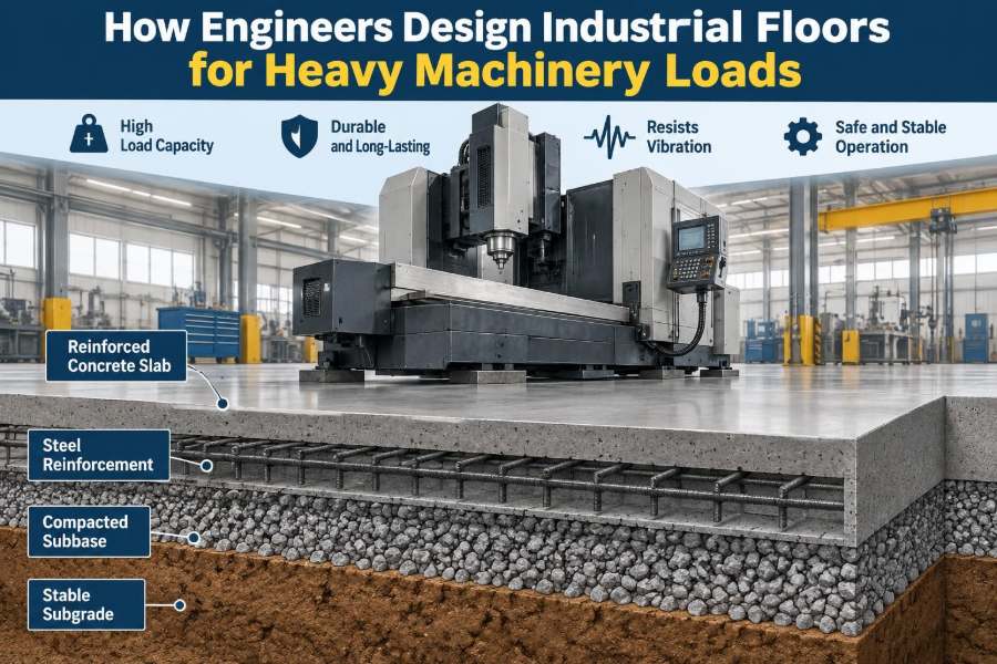

A new machining centre arrives at a factory with a transport weight measured in tens of tonnes. Its base looks broad and solid, but the machine’s actual force enters the floor through a limited number of feet, rails, anchor points, or grout pads.
If that floor settles unevenly, cracks excessively, vibrates, or allows an anchor to loosen, the problem is not merely cosmetic. Machine alignment can drift, production can stop, forklifts can be disrupted, and a repair may require removing equipment that was expensive and difficult to install.
Industrial floors are therefore not simply large slabs of concrete. They are engineered systems that transfer static loads, moving loads, impacts, vibration, and environmental actions safely into the ground.
Good design begins before concrete is specified. Engineers must understand the machine, the operation around it, the supporting soil, and the level of performance the facility actually needs. 🏭
🏭 1. Start with the real operating situation
The design question is not just, “How heavy is the machine?” A floor supporting a press, injection-moulding machine, warehouse rack, or robotic cell experiences loads in different ways and at different times.
Engineers first map how the building will operate. They identify equipment locations, vehicle routes, storage zones, maintenance access, pits, drainage channels, and future expansion areas.
- Will machinery remain fixed or be replaced periodically?
- Will forklifts turn, brake, or queue beside the machine?
- Are precise levels and low vibration essential to product quality?
- Can the machine load be shared with an isolated foundation?
📋 2. Collect reliable machine data
Equipment suppliers are a primary source of design information. Their installation drawings may state operating mass, base dimensions, support reactions, anchor layouts, centre of gravity, dynamic forces, and tolerance requirements.
Engineers should distinguish between a machine’s shipping weight and its operating load. Tooling, workpieces, coolant, moving parts, stocked material, and occasional maintenance loads may all change the forces delivered to the floor.
If data are incomplete, assumptions should be documented and resolved with the manufacturer. Designing from a nameplate mass alone can miss the most critical condition.
⚖️ 3. Separate static, dynamic, and accidental loads
Static loads act continuously or slowly, such as the self-weight of a machine. Dynamic loads vary with time because of rotating components, reciprocating parts, rolling wheels, impacts, or starts and stops.
Some actions are infrequent but still important. A dropped coil, a loaded pallet placed abruptly, or a forklift wheel near a slab edge can govern a local detail.
The designer combines applicable load cases using the governing building code and project criteria. The objective is to represent credible service and design conditions, not to apply one generic “heavy machinery” load factor everywhere.
🦶 4. Follow the load path to the ground
A safe floor has a clear load path: machine frame to feet or rails, feet to slab or foundation, slab to subbase, and subbase to subgrade. Every layer must have adequate strength, stiffness, and continuity.
A thick slab cannot compensate indefinitely for poorly prepared ground. Conversely, excellent soil may not prevent cracking beneath a highly concentrated machine support if the slab and local reinforcement are inadequate.
Thinking in load paths helps engineers locate the weak link: bearing beneath a foot, punching around a pedestal, bending between supports, joint movement, or soil deformation.
🔍 5. Understand concentrated support reactions
Machines rarely distribute weight uniformly over their plan area. Four small feet can produce much higher local stresses than the same machine weight spread over a broad baseplate.
Support reactions can also be unequal because of the centre of gravity, asymmetric tooling, moving heads, or operational forces. The maximum reaction at one location is usually more useful than the total mass when checking local floor behaviour.
Where a support includes a baseplate, grout, and anchor rods, engineers consider how those components spread force into the concrete rather than assuming perfectly uniform contact.
🚚 6. Design for vehicle traffic as well as machinery
Many industrial slabs carry both installed equipment and mobile traffic. Forklift wheels create repeated concentrated loads, especially at rack aisles, loading areas, doorways, and turning zones.
Wheel loads are affected by vehicle capacity, axle arrangement, tire type, load position, and travel pattern. Repetition matters because it can widen cracks, wear joint edges, and progressively damage weak details.
A floor that works beneath a stationary machine may still perform poorly where hard-wheeled vehicles cross joints next to it. Traffic circulation must be part of the layout review. 🚚
🧱 7. Choose the structural floor concept
Engineers select a system that suits the loads, ground conditions, construction sequence, and required performance. Common options are a slab-on-ground, a reinforced slab-on-ground, a jointed slab, a continuously reinforced slab, or a separate machine foundation.
There is no universally best choice. A conventional jointed slab may be efficient for general manufacturing, while a heavily loaded precision machine may benefit from an isolated inertia block or thickened foundation.
| System | Typical strength | Key design concern |
|---|---|---|
| Slab-on-ground | Efficient support from uniform ground | Joints, concentrated loads, and subgrade consistency |
| Reinforced slab-on-ground | Improved crack-control capacity and continuity | Reinforcement detailing and constructability |
| Separate machine foundation | Local stiffness, mass, and isolation potential | Interaction with adjacent slab and vibration response |
🌍 8. Investigate the subgrade early
The subgrade is the natural soil or engineered fill supporting the floor system. Its stiffness and uniformity influence slab deflection, bearing response, joint performance, and susceptibility to settlement.
A geotechnical investigation identifies soil layers, groundwater conditions, fill quality, compressibility, and potential problem materials. It also informs earthworks requirements and the parameters used in structural design.
Engineers should be wary of relying on a single assumed soil value across a large factory. Local soft pockets, old trenches, variable fill, and wet areas can create differential support.
🪨 9. Build a dependable subbase
A granular subbase or base course can provide a working platform, improve drainage, help achieve uniform support, and protect the subgrade during construction. It is not automatically a substitute for sound ground improvement.
The required material, thickness, moisture condition, and compaction process depend on the project. Fine-grained soils and groundwater may require additional separation, drainage, or stabilization measures.
Uniformity is often as valuable as high average stiffness. A slab can tolerate predictable support better than abrupt transitions from dense fill to soft soil.
📐 10. Size the slab for bending and shear
A slab-on-ground bends when concentrated loads cause the concrete to deflect relative to the supporting soil. Designers check critical positions such as the interior, edge, corner, and near joints or openings.
They also check local shear behaviour around highly loaded regions. The relevant failure mechanisms depend on the support geometry and whether the load acts through a plate, pedestal, wheel, or column-like element.
Slab thickness, concrete strength, reinforcement, load distribution, and foundation stiffness work together. Increasing one variable without checking the complete system can produce an inefficient or misleading solution.
🧵 11. Use reinforcement for its intended purpose
Reinforcement can control crack widths, provide continuity, carry flexural demand, support local load effects, and hold a slab together after cracking. Its purpose must be explicit in the design.
Light mesh placed near mid-depth may assist shrinkage crack control, but it does not automatically provide the structural capacity required beneath severe machinery loads. Bar size, spacing, cover, location, laps, and anchorage all matter.
Steel fibres or synthetic fibres may also be used where appropriate, but their contribution should be based on verified material properties, design method, and quality control rather than informal substitution.
🧲 12. Detail anchors and machine connections
Anchors transfer tension, shear, and sometimes cyclic forces from machinery into concrete. Their performance depends on embedment, edge distance, spacing, concrete condition, reinforcement, installation method, and the applied loading direction.
Anchor design is especially important near slab edges, pits, joints, and thin sections. Cracked concrete, repeated loading, and vibration can alter the connection behaviour from the idealized installation condition.
Installation tolerances should be coordinated before concrete is poured. Misplaced anchor groups may force drilling, redesign, or field modifications that weaken the intended detail.
🛠️ 13. Consider grout, baseplates, and levelling
Many machines are levelled on shims, wedges, or adjustable supports and then grouted beneath a baseplate. The grout creates bearing contact and helps distribute compression into the foundation.
The foundation surface must have the specified elevation, roughness, cleanliness, and edge clearance for the chosen grout system. Poor surface preparation can prevent the assumed load transfer.
Engineers also need to understand the installation sequence. A foundation that is structurally sound but impossible to level accurately does not meet the machine’s functional requirements.
📳 14. Treat vibration as a serviceability problem
Vibration may not cause immediate structural failure, yet it can affect machining accuracy, occupant comfort, sensitive instruments, bolt performance, and adjacent processes. For some equipment, vibration control is the governing requirement.
Engineers examine the machine’s forcing frequencies, the foundation mass and stiffness, the soil response, and the proximity of vibration-sensitive equipment. Rotating machinery, impact equipment, and reciprocating machines deserve different approaches.
A vibration evaluation is not simply a thicker-slab check. It is a dynamic interaction problem involving the machine, support system, and ground.
🎵 15. Avoid resonance and unwanted transmission
Resonance can occur when an operating frequency approaches a natural frequency of the machine-foundation-soil system. Under that condition, vibration amplitudes may rise significantly.
Potential solutions include changing foundation dimensions or mass, increasing stiffness, adjusting equipment operating conditions where feasible, or using an isolation system designed for the application.
Isolation has trade-offs. It can reduce transmitted vibration but may allow larger machine motion, so it must be coordinated with utilities, clearances, anchors, and alignment requirements.
✂️ 16. Plan joints rather than merely accepting them
Concrete shrinks as it dries and changes temperature. Joints provide planned locations for movement and cracking, but they can be vulnerable under heavy wheeled traffic and near machine supports.
Joint layout should account for slab geometry, columns, openings, pour sequence, rack lines, wheel paths, and equipment foundations. Random joint placement after the layout is fixed often creates maintenance problems.
Where traffic crosses joints, engineers may specify load-transfer details and durable arrises. A joint immediately beneath a precision machine foot is usually an avoidable complication.
🧩 17. Isolate independent foundations where needed
A separate machine foundation may be intentionally isolated from the surrounding slab with a compressible joint or gap. This allows relative movement and can reduce direct vibration transmission.
However, isolation must be complete and practical. Reinforcing bars, rigid grout bridges, embedded conduits, or debris lodged in the gap can unintentionally reconnect the two elements.
The surrounding floor still needs a safe transition. Edges around isolated blocks may need protection from forklifts and may require coordinated joint or armouring details.
💧 18. Control water beneath and on the floor
Water can soften susceptible subgrades, erode fines, create pumping under repeated loads, and contribute to corrosion or freeze-related damage in relevant climates. Moisture management is a structural durability issue.
Site drainage, underfloor drainage where required, vapor management, plumbing coordination, and slab falls should be resolved together. Process washdown areas may have very different requirements from dry manufacturing zones.
Surface drainage should not direct water toward machine bases, pits, or unsealed joints. Maintenance access to drains also matters in working facilities.
🧪 19. Specify concrete for placement and durability
Concrete selection balances structural strength, workability, shrinkage behaviour, finishing needs, exposure conditions, and curing requirements. Higher specified strength alone does not guarantee better floor performance.
Large industrial placements demand a mix that can be transported, placed, consolidated, and finished consistently. Excessive water addition on site can increase shrinkage and reduce surface quality.
Where chemicals, oils, thermal exposure, abrasion, or wet service are expected, the concrete system and any protective treatment should be selected for that environment.
✨ 20. Design the surface for the operation
The top few millimetres of an industrial floor receive tire abrasion, sliding loads, spills, impacts, and cleaning actions. Surface flatness, hardness, texture, and finish affect both productivity and safety.
High-tolerance equipment or automated guided vehicles may require closely controlled floor profile criteria. General production areas may prioritize a durable, practical finish instead.
Surface hardeners, coatings, and sealers can be useful in appropriate environments, but they do not correct a structurally inadequate slab or poorly constructed joint.
📏 21. Set realistic levelness and flatness criteria
Floor tolerances should be tied to use. A production line with precision alignment, narrow-aisle storage equipment, and a conventional workshop do not require identical floor geometry.
Engineers and owners should state where stringent tolerances apply and how they will be measured. Local requirements around machine foundations can be more important than a uniform requirement over the entire building.
Very tight tolerances influence pour sizes, screeding method, survey control, construction joints, timing, and corrective work. They must be specified early, not requested after placement.
🔥 22. Account for temperature and thermal movement
Industrial floors may experience heat from furnaces, hot materials, process equipment, solar exposure at doorways, or cold-room operations. Temperature gradients can cause curling, restraint stresses, and movement at joints.
Machine foundations with heat-generating equipment may need special consideration for thermal expansion and temperature effects on alignment. Nearby slabs can move differently from thick foundations.
Details around embedded services, drains, and transitions should allow the floor to respond without creating uncontrolled cracks or damaging finishes.
🔌 23. Coordinate pits, trenches, and embedded services
Electrical conduits, process lines, drainage channels, pits, and sleeves interrupt the concrete and can weaken a load path. Their locations must be coordinated with reinforcement, joints, anchors, and machine supports.
A trench near a machine foot can create an unintended edge condition. A sleeve through a heavily loaded area may require local reinforcement or a revised equipment layout.
Three-dimensional coordination before construction is valuable because cutting a completed industrial slab to install overlooked services can be disruptive and structurally consequential.
🚧 24. Make construction sequencing part of the design
Floor performance depends heavily on execution. The design should communicate formation preparation, subbase acceptance, reinforcement support, pour boundaries, joint timing, curing, and protection from early traffic.
Construction joints should be located deliberately and detailed for the intended load transfer. Pour sequence can affect restraint, curling, access, and the ability to maintain tolerance.
Engineers should also define when heavy machinery may be installed. Concrete strength gain, grout curing, anchor installation, and subgrade protection all influence the safe commissioning sequence.
✅ 25. Verify quality before the machinery arrives
Quality assurance starts with inspection of the prepared formation and continues through material testing, placement observation, curing, joint cutting, and survey checks. Records make later troubleshooting far easier.
Useful verification may include checking elevations, slab thickness at agreed locations, reinforcement placement before the pour, anchor coordinates, joint layout, and achieved floor tolerances.
Testing should answer project-specific questions. A long list of generic tests is less valuable than targeted checks on the details that control performance.
🔧 26. Plan for maintenance, modification, and repair
Industrial facilities evolve. Machines are upgraded, routes change, new anchors are drilled, and racks are rearranged. A good floor design leaves clear documentation of slab thickness, reinforcement, joints, services, and foundation limits.
Before coring, cutting, or installing post-installed anchors, the owner should review records and assess the proposed work. Unplanned penetrations can strike reinforcement, sever services, or reduce capacity at critical locations.
Repair strategies for cracks, joint damage, settlement, or worn surfaces should address the cause as well as the visible symptom. Cosmetic patching alone rarely solves an active support problem.
🧠 27. Apply the core principle: design the whole support system
The strongest industrial floor designs do not focus only on concrete thickness. They connect machine reactions, operational traffic, ground conditions, structural behaviour, joints, vibration, installation details, and construction quality into one coordinated system.
For straightforward equipment, that system may be a carefully designed slab-on-ground. For demanding equipment, it may include a dedicated foundation, isolation measures, enhanced reinforcement, specialized grouting, and stringent tolerance control.
The core principle is simple: heavy machinery performs reliably only when every part of its load path—from the machine connection to the supporting soil—is designed and built to work together. 🏭📐✅